Monochromator principles
of operation
Although many detailed variations are possible, most monochromators are of the same basic
design, which is generally known as the Czerny-Turner configuration, and ours is no exception.
Its operation is quite easy
to understand, but this topic is
not well covered by
standard optical texts, and we therefore
give a basic description here. This description will also explain
the particular features of our
own design, and will also explain
the very important interaction between bandwidth and optical throughput,
which our real-time slit width control system
can fully exploit. The standard Czerny-Turner configuration is shown below.
Light from an appropriate source (a xenon arc in our case) is
focussed onto an input slit, and light passing
through this slit is collimated by a concave mirror, which also reflects
it onto a diffraction grating. The grating in turn directs the
light onto a second concave mirror, which reflects
and focusses it onto an
exit slit before it leaves the instrument. Mirrors are used rather than lenses
because they do not introduce any chromatic
aberration, but they do introduce other aberrations which limit the resolution of the
instrument, as will be discussed shortly. Since the redirection
of the light
beam by the grating is actually
a diffraction rather than an ordinary
reflection, the grating disperses the beam, i.e.
different wavelengths leave the grating
at different angles. By rotating the grating about
its central axis, we can
vary the range of wavelengths which can be
reflected and focussed by the second mirror onto
the exit slit.
Standard Czerny-Turner configuration
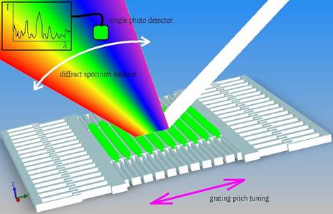
The figure below
shows how a reflective grating works. This is
a horizontal section through the grating,
which resembles a saw blade. Viewed
face on, the "teeth"
are actually grooves, and the two
slits in the instrument are
parallel with them. (Slits can
be used rather
than circular apertures because the grating disperses
light only in the horizontal direction, so by lengthening the apertures in the vertical direction we can get
more light through the instrument without losing any resolution).
Imagine a light beam arriving at
a direction perpendicular
to the grating. If the grating
just acted as a mirror, the beam
would be reflected straight back again, and
indeed, some proportion of the
light is reflected in this way, but in this
case it is
referred to as the zero-order diffracted
beam. However, the grooves are shaped so that
most of the light leaves the
grating at a different angle, corresponding to the first-order diffracted
beam. This angle corresponds to the one where
reflections f rom adjacent teeth give optical patch
length differences of exactly one
wavelength. Since the angle is
therefore wavelength-dependent, the diffracted beam actually forms a spectrum, from which we can
select the required wavelengths by focussing them onto the exit slit.
Principle of operation of reflection
grating
In the Czerny-Turner configuration, this is done
by rotating the grating so that
the required wavelength is always
reflected at the same angle.
This means that the angle
of the incoming
light also changes, but that
doesn't have any major impact apart from making
the calculations somewhat more interesting. The angles of
the incoming and outgoing beams
are conventionally referred
to as a and b respectively, and although they both
change when the grating is
rotated, the difference between them, conventionally referred to as D, remains constant. Note that a and b are both measured with
respect to the grating normal, and they will
be of opposite
signs if they are on opposite sides of the
grating normal.
The basic grating
equation is given by:
![]()
where l is the
wavelength in nm, k is the diffraction order and n is
the number of lines per mm for the grating.
This can be rearranged in terms of the
wavelength to give:
For a given instrument the deviation D is fixed and
given by:
![]()
so we can
express b in terms of
D and a and then solve for
a to obtain:
For reference, n for our standard grating is 1200 lines/mm, k is always 1 (i.e. first-order
diffraction) and D in our instrument is 20 degrees. The sensitivity of the electrical
input which controls the grating
angle is 0.25 volts per degree. Users who wish
to make their own arrangements for driving the
monochromator can therefore substitute these values
into equation (4) in order to calculate the appropriate drive voltage for a given
wavelength. However, users who also
have our microprocessor control box do not
need to become involved with any
of this, as the microprocessor performs these calculations itself, so the
required wavelengths can be specified
directly.
There are also maxima corresponding to path length differences of two or
more wavelengths, giving second- and other
higher-order diffracted beams (this series continues
up to the maximum possible diffracted angle of 90 degrees),
and there is another complete
set of diffracted beams at the
same angles on the other side
of the incoming
beam. However, by appropriately shaping the grooves in the grating, which
is termed blazing, it is
possible to direct most of the diffracted
light into a particular ONE of these several destinations, over a reasonably wide range of wavelengths.
The wavelength at which this
occurs most efficiently is known as the
blaze wavelength, and we use a grating with a blaze wavelength of 400nm in order to obtain highest grating efficiency (of around 70% into
the required first order diffracted
beam) in the near UV, for
optimum results with indicators such as fura-2 and indo-1. However,
the efficiency is still above
50% over most of the visible spectrum
too.
Although a number of
other configurations have been described,
nothing else seems able to beat
the performance of the Czerny-Turner, particularly in respect of the (for
biological fluorescence applications)
requirement for high optical throughput,
which we discuss below. In our opinion the
only viable alternative is one in which the
grating itself is concave, so
that the two concave mirrors
are no longer required. However, the substantially
higher cost of such gratings (which must be
custom designed) makes the instrument more expensive overall. Conventional plane gratings are
much cheaper, and our suppliers can
provide gratings with almost any
required characteristics at the same
relatively low cost. The standard grating we supply
has 1200 line lines/mm, blazed
at 400nm, since we believe it
represents the best overall compromise
for this type of instrument. However, just about any
other required characteristic can be supplied to special order.
Grating